This is a try at creating an audio switch that will select between two destinations for a single stereo audio signal.
Introduction
The idea behind this is to permanently plug the output of my PC to the speakers and the tv but only select one at a time so that they don't "parasite" each other. I wanted to be able to switch at the push of button, and I know that I can find DPDT latching buttons, but out of curiosity, I wanted to have an electronics based solution. This is the result of discussions in sci.electronics.design and should work but has not been made yet.
The schematic
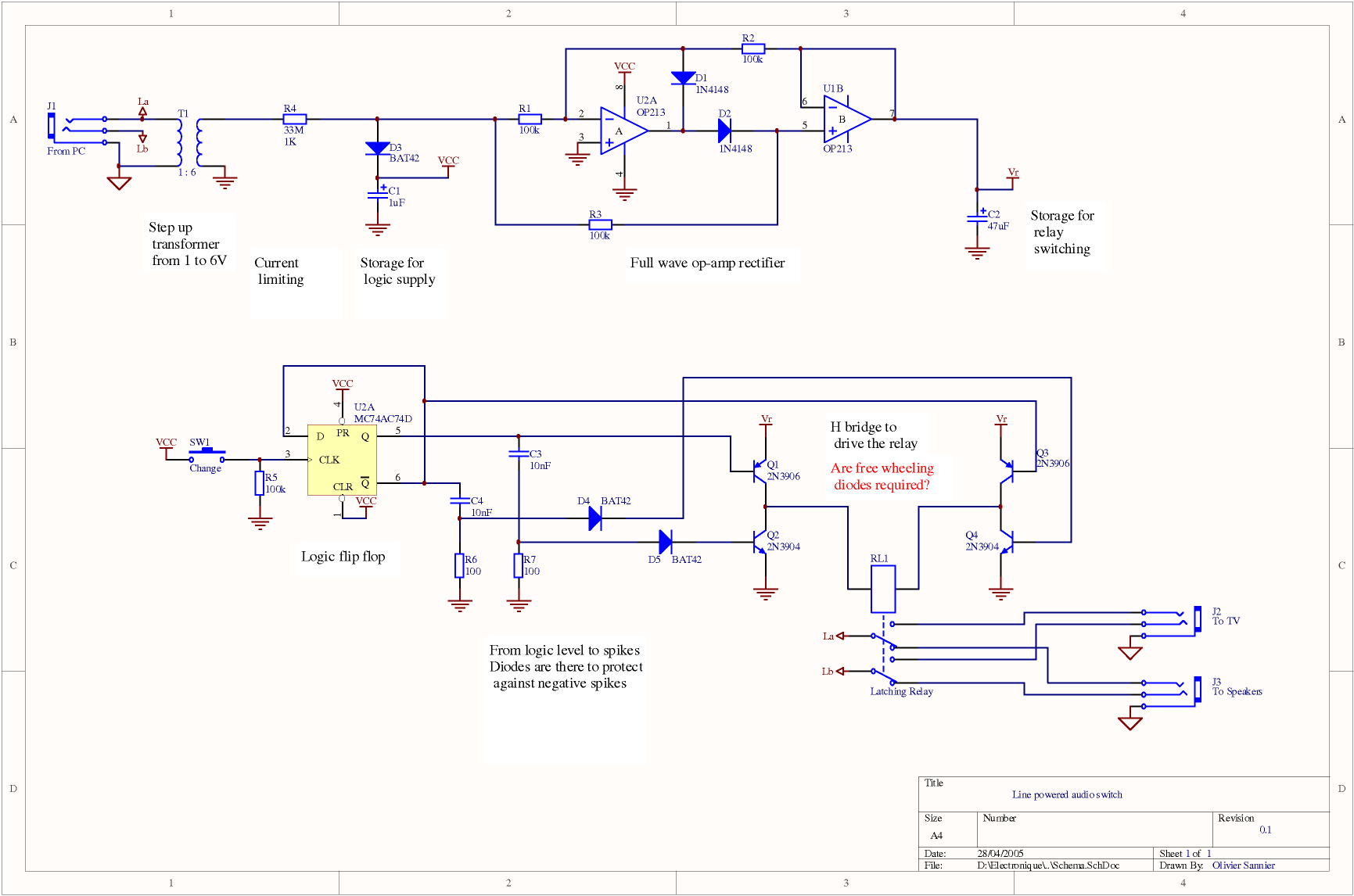
Here is the first attempt at the schematic
Working principles
The audio line provides, at best, 1.5V and we can draw about 1mW from it without killing it.
We elevate this 1.5V to about 7V using the transformer and the full wave op amp is used to make a positive voltage out of this. Op amps are used instead of a classical diode bridge because of the low voltages involved.
Because we can't draw much current from the line, we limit what goes out of the rectifier with a very big resistor.
We store whatever we can in capacitors so that it can be used later on. The smallest one is for the logic (op amps and d flip flop) as it does not require much, and the bigger one is for switching the relay. Considering how little current we get, the capactiors charge up takes well over a second. But that's not a problem for this application.
The D-Type flip flop will store the state of the previously selected line. Push the button and it's Q output will go from Low to High or High to Low depending on it's previous state.
In order for us not to permanently draw current from the line, we don't want to use logic levels to connect the relay coil to the storage capacitor C2. We want it to be connected for a very short time, hence we need to convert the level into a spike, when it changes.
For this, we use a RC network and use the voltage accross the resistor as it is the exact complement to the one accross the capacitor. We make the RC constant small so as to have a very short spike. Starting with an initial low level, the capacitor is discharged and the voltage accross the resistor is null (Vc+Vr=0). When a high level comes in, the capacitor charges and the voltage accross the resistor suddenly goes to Vhigh, and then goes down as the capacitor charges, so as to keep this equation true: Vc+Vr = Vhigh
This is fine, but when the signal goes from high to low, the capacitor is still charged, hence the voltage accross the resistor has to be negative so as to keep Vc+Vr=0 true. This negative spike can have a bad impact on the circuit connected to it, hence the need to maybe prevent it reaching the bridge with a series diode.
The H bridge is used to drive the current from C2 into the coil one way or the other depending on the status of the Q output in U2. The NPN (2N3904) transistors are only opened for the duration of the spike, hence ensuring that current is not drawn permanently into the coil, thus allowing C2 to charge again.