This article presents how I have reused my dead Presario 2710 laptop and turned it into a KVM console for my server
Introduction
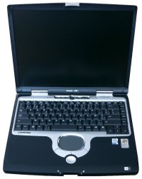
The Presario 2710 was my laptop during the 2002-2008 years. It died a first time in 2003, the motherboard wouldn't supply any current anymore. I had it repaired (cost me a fortune) but when it died again with the same symptoms in 2008, I decided to put it back to rest.
At that time, I though about reusing the LCD panel as a secondary monitor for my new PC, but I couldn't find any documentation apart from the fact that converting VGA to LVDS would be difficult, especially without the proper pinouts for the different connectors.
Zoom fast to 2015 where I discover that LCD converter boards are available on eBay and the interest on that dead laptop rises again.
This article details the process that I followed to reuse the laptop.
Opening the laptop isn't so much a deal in itself.
Basically, remove all the screws you can find at the back and everything should come apart easily.
Removing the motherboard from the shell is a bit tricky because it is held to the case via the VGA connector side screws. Once these are removed, the motherboard is free and can be taken out.
The keyboard and trackpad are connected to their controller boards via flatflex cables and drawer type connectors. Slide a small screwdriver on the side to open the drawer and the ribbons will come out easily.
Make sure to preserve the trackpad assembly, it is easily reusable.
The LCD frame is attached with screws that are hidden beneath the soft rubber cushions. Once removed, you will find that the frame is also clipped, so simply gently pull it apart and you'll access the panel which is itself screwed to the backframe.
LCD Panel
According to the label on its back, the LCD Panel is a LQ150X1LH82 made by Sharp.
Its resolution is 1024x768 and I believed it was 16M capable, at least according to Compaq when the laptop was sold.
Trying to find a pinout for it borders on the impossible, the manufacturer does not want to release it. There is this site however:
http://www.panelook.co...eter_10126.html
Where one discovers that the panel is actually only 6 bits capable, meaning only 262144 distinct colors. Well, for a KVM console that will be enough, but for a "top of the range" laptop, that was a bit of a scam.
Controller board
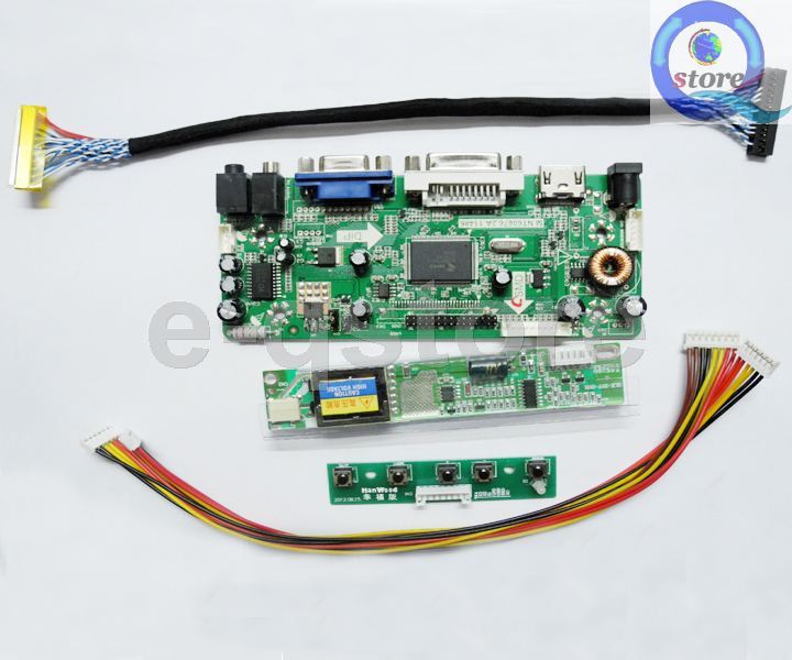
On eBay, you can find lots of different sellers for what is called "Screen Controller Board Kit" where one gets all that is needed to turn a bare LCD into a complete monitor:
- converter board
- control panel
- backlight module
- LVDS interface cable
- connection cables
The only thing that needs to be bought separetly is a 12V 4A power supply.
As I was interested in versatily, I wanted DVI, VGA and HDMI. Also, because the laptop has integrated speakers, I looked for kits that included audio.
The perfect kit looked to be one called M.NT68676.2A and it was sold by "e-qstore". Here is a picture:
Before purchasing the kit, I contacted the seller who said it should be ok.
After a few weeks, I received it, plugged it, and... it did not work. Here is a short video of its behavior:
https://www.youtube.com/watch...BQpfdzCZo
As you can see, the backlight turns on just fine but there are lines on top of each other where I expected to see a "no signal" message in the middle of the screen.
The support from e-qstore was really excellent and after another few weeks, I received a board from a different kit that they thought should work better. It's the one from this kit, based on the VST29 chip:
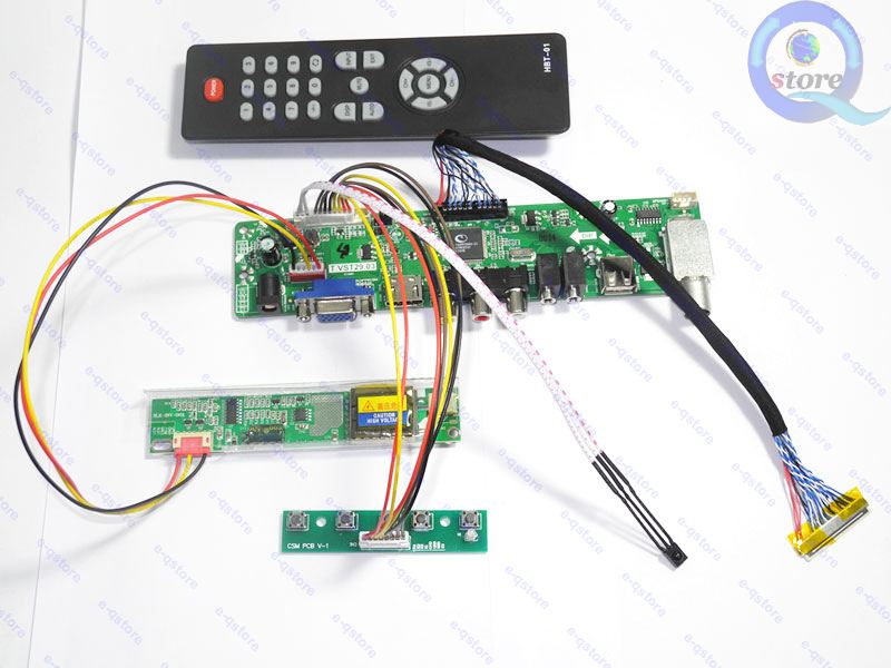
Once I received the board, I connected it to the panel and it worked beautifully!
I lost the DVI functionnality, but at least I have a working LCD panel.
Retrofitting
As I want to have a most discrete reuse, I intend on putting every board inside the body of the laptop. There is ample room for everything, once the hardrive, floppy drive, battery and DVD drive are removed.
This means that the LVDS cable that goes from the LCD to the controller board needs to be long enough, which is roughly 40cm. Unfortunately, the default kit only contains a 26cm cable, so make sure to indicate you need the longer length cable before ordering. This would avoid ordering it separetely and waiting for another few weeks for its arrival.
The backlight module in the kit is way too big when compared to the orignal one and so it won't fit at the base of the LCD assembly as the original one did. Here is a photo of the orignal one:
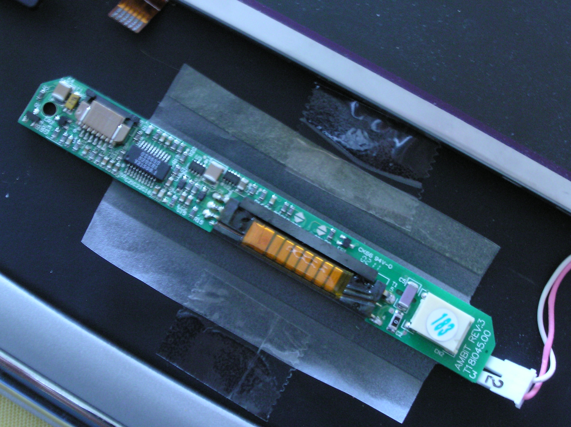
Looking closely at the chip near the drawer connector, I discovered that it is a OZ960S chip, a fairly common CCFL controller.
The kit outputs 12V for its backlight module power pins and 5V on its enable pint. The OZ960S requires the 12V on the power pins but also a 5V power rail to function properly. Fortunately, the controller board above outputs a regulated 5V on its interface connector.
Using this to power the original inverter board works just fine and allows to fit everything back into place.
Keyboard and touchpad
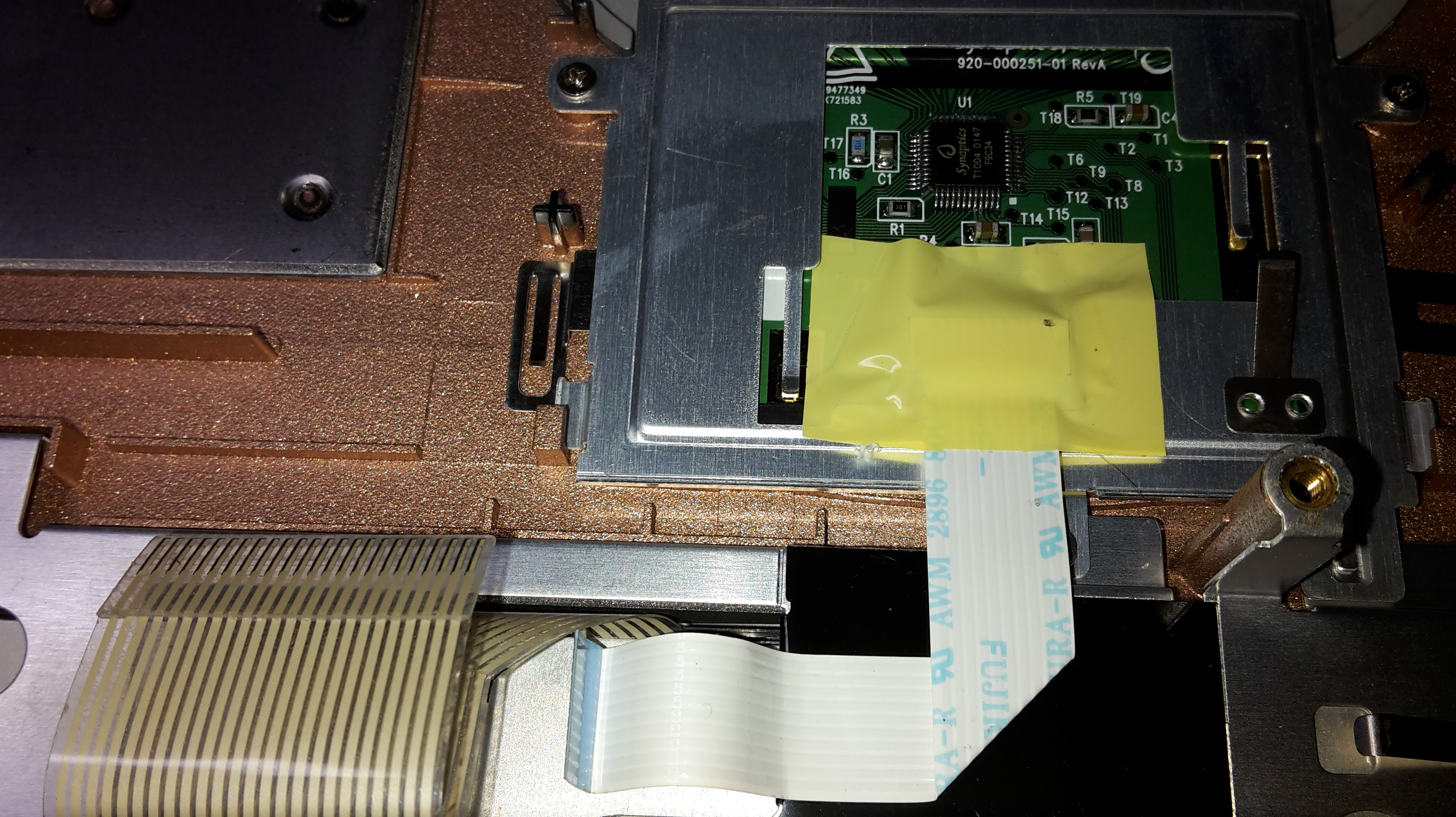
Here is a picture of the touchpad and keyboard on the inner side of the laptop:
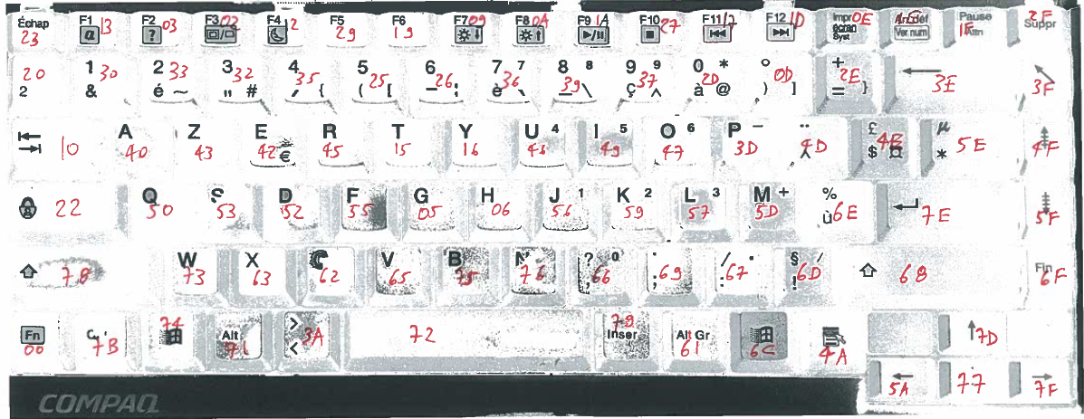
The keyboard is connected to the motherboard via a flatflex 24 pin ribbon and a drawer type connector. Tracing the lines around the database, I discovered all 24 lines end up on a big chip made by National Semiconductor, the PC87570. It has 16 KBSOUT lines and 8 KBSIN lines, all connected to the 24 pins of the ribbon connector going to the matrix. The pinout is as follows:
| Flatflex | 1 | 2 | 3 | 4 | 5 | 6 | 7 | 8 | 9 | 10 | 11 | 12 | 13 | 14 | 15 | 16 | 17 | 18 | 19 | 20 | 21 | 22 | 23 | 24 |
| KBSIN | 0 | 1 | 2 | 3 | 4 | 5 | 6 | 7 | ||||||||||||||||
| KBSOUT | 0 | 11 | 4 | 8 | 3 | 5 | 6 | 9 | 7 | 10 | 13 | 14 | 12 | 2 | 1 | 15 |
The touchpad on the laptop is made by Synaptics, and uses the T1004 ASIC. You can look around the web for its datasheet, I don't think you will find it. It is connected to the motherboard with yet another flatflex ribbon, a 10 pin one this time. Tracing the lines around on the motherboard, I discovered that it is connected on the PC87570 auxiliary PS/2 interface. This means that it outputs PS/2 signal, which is the default signal for mouses.
This confirms what I found when looking for the T1004 ASIC datasheet and pinout:
Tracing a bit more, I found the complete pinout, which is as follows:
| Signal | Flatflex pin | T1004 pin |
| Vcc | 1 | 45 |
| PS/2 Data | 2 | 2 |
| PS/2 Clock | 3 | 3 |
| Right click | 4 | 6 |
| Left click | 5 | 7 |
| GND | 6 | 44 |
| Up scroll | 7 | 8 |
| Down scroll | 8 | 9 |
| Left scroll | 9 | 10 |
| Right scroll | 10 | 11 |
When you place the T1004 mark at the bottom left, pin 1 is the first at the bottom and numbering is done counterclockwise.
All buttons are "active low" switches, that is, the switches connect the line to ground when they are closed to indicate the related action.
Connecting to a PC
While the touchpad uses a failry common PS/2 protocol, USB is much more common these days. A simple PS/2 to USB converter would work, but that leaves the keyboard by itself because we need a specialized chip that scans the matrix and sends the appropriate elements over the USB bus.
Browsing around the web, I found the Sprintek SK5000 family of controller chips that appear to have all that is needed: http://sprintek.com/pr...s/Keyboard.aspx
They even have a nice graphical interface that allows to program the chip to match the physical matrix.
However, they are not cheap, and difficult to come by in France. With shipping costs included, the total would be around 30€ just for the chip itself. Considering it's only available in QFN packages and that I don't have the required equipment to do reflow soldering, along with the fact that I would need to create a board for it, I decided to look for alternatives.
Fortunately, there is a very good alternative, the TMK keyboard firwmare. It requires a Teensy board which is definitely easier to come by, cheaper, and has the very nice advantage of being available completely soldered. I only had to add the 100mil headers, which is definitely something I could do with the equipment I have.
What's very nice is that it has a fully functional USB interface, and the firmware allows a composite mode where it declares itself as a USB keyboard and USB mouse. It effectively translates the matrix and PS/2 signals into USB packets.
The matrix has 24 pins, I needed 2 more for the PS/2 signal which means that with 25 I/O pins, the Teensy 2.0 does not have enough of them. Fortunately, the Teensy++ 2.0 has more pins (46) which means that I could even use one of its PWM outputs to drive the DIM pin on the LCD backlight controller. I mean, there are Fn combinations for doing just that directly printed on the matrix itself.
As I was a bit new in the AVR and TMK world, I started discussion threads on the following two boards:
They have proven to be of great help and patience.
To make things clearer, I have created a fork of TMK's project and a specific branch for my customization at GitHub. You may want to have a look a the commit history to discover what I needed to customize.
Reverse engineering the matrix
The most tedious part in the keyboard process is figuring out the matrix key assignment.
The only way to do that is to hook the keyboard to a breadboard with 16+8 leds that show which show which row and column are activated when a key is pressed. Here is a picture of the setup:
(yet to come, waiting on the flatflex connectors and breakout boards)
This needs to be done around 100 times and allows to have the following result:
This is then added in the firmware configuration and downloaded into the Teensy.
Now that everything works, it is now time to make sure it fits into the (empty) notebook so that it looks conspicuous enough.
The cleanest thing was to reuse the buttons at the top and the VGA connector at the back.