Keyboard and touchpad
Here is a picture of the touchpad and keyboard on the inner side of the laptop:
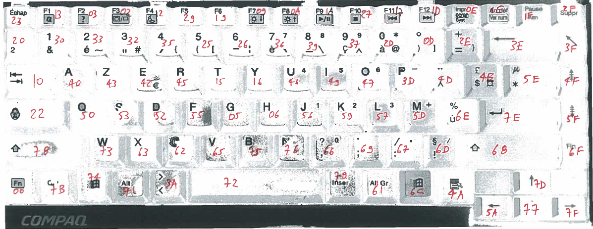
The keyboard is connected to the motherboard via a flatflex 24 pin ribbon and a drawer type connector. Tracing the lines around the database, I discovered all 24 lines end up on a big chip made by National Semiconductor, the PC87570. It has 16 KBSOUT lines and 8 KBSIN lines, all connected to the 24 pins of the ribbon connector going to the matrix. The pinout is as follows:
| Flatflex | 1 | 2 | 3 | 4 | 5 | 6 | 7 | 8 | 9 | 10 | 11 | 12 | 13 | 14 | 15 | 16 | 17 | 18 | 19 | 20 | 21 | 22 | 23 | 24 |
| KBSIN | 0 | 1 | 2 | 3 | 4 | 5 | 6 | 7 | ||||||||||||||||
| KBSOUT | 0 | 11 | 4 | 8 | 3 | 5 | 6 | 9 | 7 | 10 | 13 | 14 | 12 | 2 | 1 | 15 |
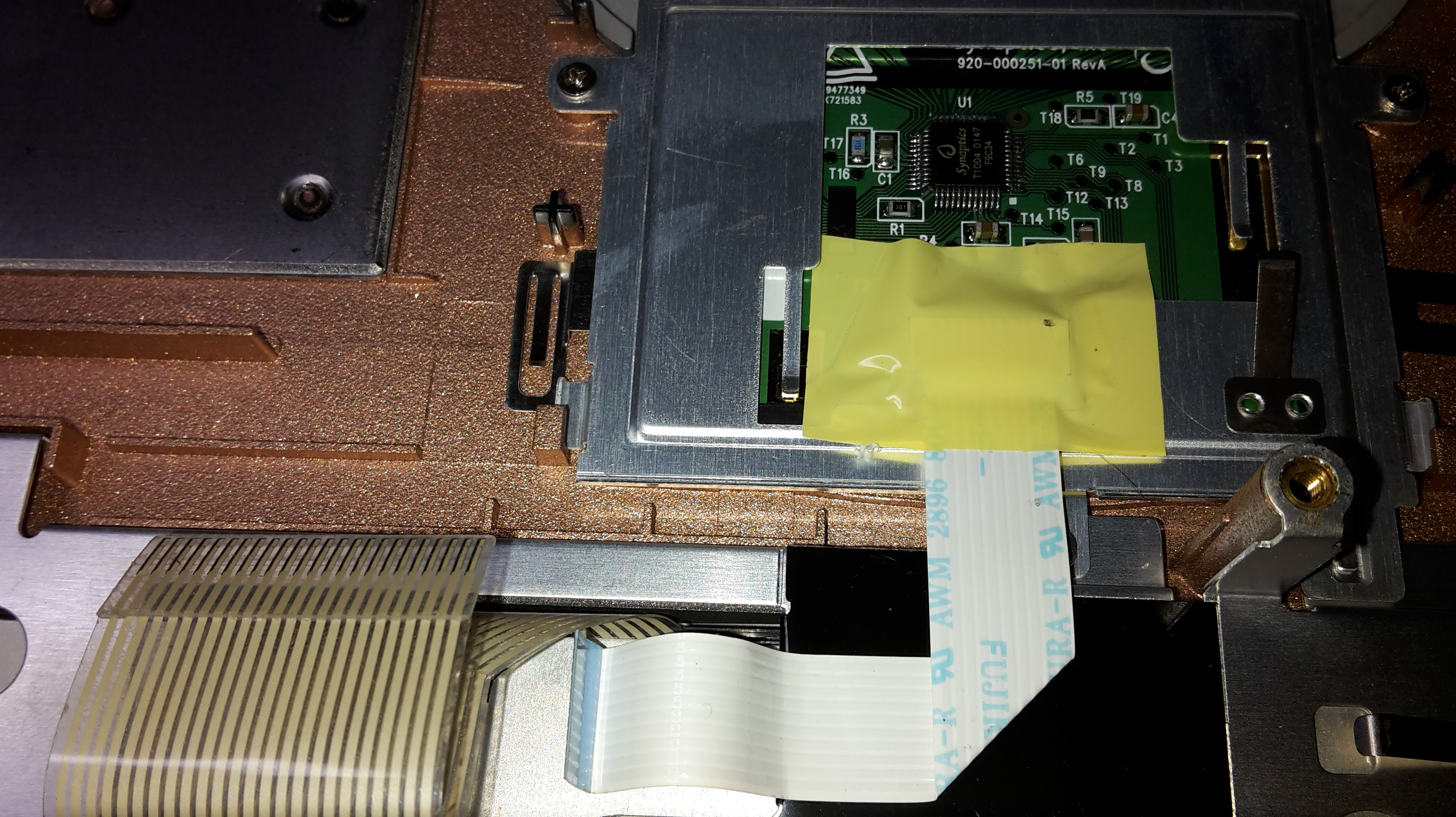
The touchpad on the laptop is made by Synaptics, and uses the T1004 ASIC. You can look around the web for its datasheet, I don't think you will find it. It is connected to the motherboard with yet another flatflex ribbon, a 10 pin one this time. Tracing the lines around on the motherboard, I discovered that it is connected on the PC87570 auxiliary PS/2 interface. This means that it outputs PS/2 signal, which is the default signal for mouses.
This confirms what I found when looking for the T1004 ASIC datasheet and pinout:
Tracing a bit more, I found the complete pinout, which is as follows:
| Signal | Flatflex pin | T1004 pin |
| Vcc | 1 | 45 |
| PS/2 Data | 2 | 2 |
| PS/2 Clock | 3 | 3 |
| Right click | 4 | 6 |
| Left click | 5 | 7 |
| GND | 6 | 44 |
| Up scroll | 7 | 8 |
| Down scroll | 8 | 9 |
| Left scroll | 9 | 10 |
| Right scroll | 10 | 11 |
When you place the T1004 mark at the bottom left, pin 1 is the first at the bottom and numbering is done counterclockwise.
All buttons are "active low" switches, that is, the switches connect the line to ground when they are closed to indicate the related action.
Connecting to a PC
While the touchpad uses a failry common PS/2 protocol, USB is much more common these days. A simple PS/2 to USB converter would work, but that leaves the keyboard by itself because we need a specialized chip that scans the matrix and sends the appropriate elements over the USB bus.
Browsing around the web, I found the Sprintek SK5000 family of controller chips that appear to have all that is needed: http://sprintek.com/pr...s/Keyboard.aspx
They even have a nice graphical interface that allows to program the chip to match the physical matrix.
However, they are not cheap, and difficult to come by in France. With shipping costs included, the total would be around 30€ just for the chip itself. Considering it's only available in QFN packages and that I don't have the required equipment to do reflow soldering, along with the fact that I would need to create a board for it, I decided to look for alternatives.
Fortunately, there is a very good alternative, the TMK keyboard firwmare. It requires a Teensy board which is definitely easier to come by, cheaper, and has the very nice advantage of being available completely soldered. I only had to add the 100mil headers, which is definitely something I could do with the equipment I have.
What's very nice is that it has a fully functional USB interface, and the firmware allows a composite mode where it declares itself as a USB keyboard and USB mouse. It effectively translates the matrix and PS/2 signals into USB packets.
The matrix has 24 pins, I needed 2 more for the PS/2 signal which means that with 25 I/O pins, the Teensy 2.0 does not have enough of them. Fortunately, the Teensy++ 2.0 has more pins (46) which means that I could even use one of its PWM outputs to drive the DIM pin on the LCD backlight controller. I mean, there are Fn combinations for doing just that directly printed on the matrix itself.
As I was a bit new in the AVR and TMK world, I started discussion threads on the following two boards:
They have proven to be of great help and patience.
To make things clearer, I have created a fork of TMK's project and a specific branch for my customization at GitHub. You may want to have a look a the commit history to discover what I needed to customize.
Reverse engineering the matrix
The most tedious part in the keyboard process is figuring out the matrix key assignment.
The only way to do that is to hook the keyboard to a breadboard with 16+8 leds that show which show which row and column are activated when a key is pressed. Here is a picture of the setup:
(yet to come, waiting on the flatflex connectors and breakout boards)
This needs to be done around 100 times and allows to have the following result:
This is then added in the firmware configuration and downloaded into the Teensy.